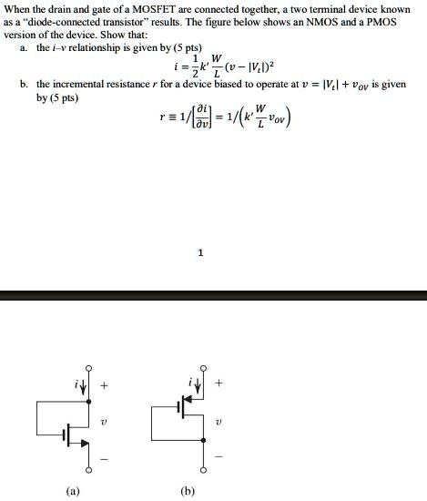
When the drain and gate of a MOSFET are connected together, a two terminal device known as a \"diode-connected transistor\" results.
The Correct Answer and Explanation is:
Here is the step-by-step derivation for the given relationships.
Part a: The i-v relationship
The problem asks to show that the current-voltage (i-v) relationship for a diode-connected MOSFET is given by:
i = (1/2) * k’ * (W/L) * (v – |Vt|)^2
- Circuit Configuration: In a diode-connected configuration, the drain and gate terminals of the MOSFET are connected. This means the gate-to-source voltage (v_GS) is equal to the drain-to-source voltage (v_DS). Let’s call this common voltage v, so v_GS = v_DS = v.
- Operating Region: A MOSFET operates in the saturation region when v_GS > |Vt| and v_DS ≥ v_GS – |Vt|.
- The first condition, v > |Vt|, ensures the transistor is turned on and conducting current.
- Let’s check the second condition. Substituting v_GS = v and v_DS = v, the inequality becomes v ≥ v – |Vt|. This simplifies to 0 ≥ -|Vt|, which is always true since the threshold voltage |Vt| is a positive value.
- Therefore, whenever the diode-connected transistor is on (i.e., v > |Vt|), it is guaranteed to be operating in the saturation region.
- Saturation Current Equation: The standard equation for the drain current i_D of a MOSFET in saturation is:
i_D = (1/2) * k’ * (W/L) * (v_GS – |Vt|)^2
Here, k’ is the process transconductance parameter, W/L is the aspect ratio of the transistor, and Vt is the threshold voltage. - Final Derivation: By substituting our circuit’s conditions (i = i_D and v = v_GS) into the saturation equation, we directly obtain the required i-v relationship:
i = (1/2) * k’ * (W/L) * (v – |Vt|)^2
Part b: The incremental resistance
The problem asks to show that the incremental resistance r at a bias point v = |Vt| + V_ov is given by:
r = 1 / [∂i/∂v] = 1 / (k’ * (W/L) * V_ov)
- Definition of Incremental Resistance: The incremental resistance r is defined as the inverse of the slope of the i-v curve at a specific operating point. Mathematically, r = 1 / (∂i/∂v).
- Differentiate the i-v Relationship: We start with the equation derived in Part (a) and differentiate the current i with respect to the voltage v:
∂i/∂v = d/dv [ (1/2) * k’ * (W/L) * (v – |Vt|)^2 ]
Using the chain rule for differentiation, we get:
∂i/∂v = (1/2) * k’ * (W/L) * 2 * (v – |Vt|)^(2-1) * (d/dv(v – |Vt|))
∂i/∂v = k’ * (W/L) * (v – |Vt|) - Apply the Bias Point: The expression is evaluated at the given bias point. The overdrive voltage, V_ov, is defined as the amount by which the gate-source voltage exceeds the threshold voltage: V_ov = v_GS – |Vt|.
Since v_GS = v in this circuit, we have V_ov = v – |Vt|. - Final Derivation: We can substitute V_ov into our expression for the derivative:
∂i/∂v = k’ * (W/L) * V_ov
Finally, we find the incremental resistance r by taking the reciprocal of this expression:
r = 1 / (∂i/∂v) = 1 / (k’ * (W/L) * V_ov)