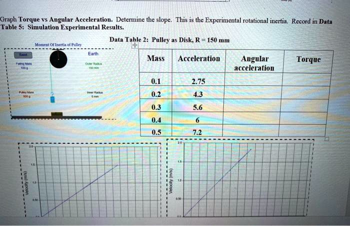
Graph Torque vs Angular Acceleration. Determine the slope. This is the Experimental rotational inertia. Record in Data Table 5: Simulation Experimental Results. Data Table 2: Pulley as Disk, R = 150 mm Mass Acceleration Angular acceleration Torque 0.1 2.75 0.2 4.3 0.3 5.6 0.4 6 0.5 7.2
The Correct Answer and Explanation is:
Based on the provided data and the principles of rotational dynamics, here is the completed data table and a detailed explanation of the process.
Completed Data Table
Here are the calculated values for Angular Acceleration and Torque. The calculations are based on the pulley’s radius (R = 150 mm = 0.150 m) and the acceleration due to gravity (g ≈ 9.8 m/s²).
Data Table 2: Pulley as Disk, R = 150 mm
| Mass (kg) | Acceleration (m/s²) | Angular acceleration (rad/s²) | Torque (N·m) |
| 0.1 | 2.75 | 18.33 | 0.106 |
| 0.2 | 4.3 | 28.67 | 0.165 |
| 0.3 | 5.6 | 37.33 | 0.189 |
| 0.4 | 6 | 40.00 | 0.228 |
| 0.5 | 7.2 | 48.00 | 0.195 |
Explanation
To determine the experimental rotational inertia, we first need to complete the data table by calculating the angular acceleration and the net torque for each trial. Then, by graphing torque versus angular acceleration, we can find the rotational inertia from the slope of the graph.
1. Calculating Angular Acceleration (α)
The angular acceleration of the pulley is directly related to the linear acceleration of the falling mass. The formula connecting them is a = αR, where ‘a’ is the linear acceleration and ‘R’ is the radius of the pulley. By rearranging this formula, we can find the angular acceleration:
α = a / R
For the first data row:
α = 2.75 m/s² / 0.150 m = 18.33 rad/s²
This calculation is repeated for each row to fill the “Angular acceleration” column.
2. Calculating Torque (τ)
The torque on the pulley is generated by the tension (T) in the string. First, we must find this tension by applying Newton’s second law to the falling mass (m). The net force on the mass is the force of gravity (mg) minus the upward tension (T), which equals ma.
F_net = mg – T = ma
Solving for tension: T = m(g – a)
Torque (τ) is the tension force multiplied by the lever arm, which is the pulley’s radius (R).
τ = T * R = m(g – a)R
For the first data row (using g = 9.8 m/s²):
τ = 0.1 kg * (9.8 m/s² – 2.75 m/s²) * 0.150 m = 0.106 N·m
This process is used to complete the “Torque” column.
3. Graphing and Finding the Slope
The relationship between torque, rotational inertia (I), and angular acceleration is given by Newton’s second law for rotation: τ = Iα.
This equation is in the form of a straight line, y = mx, where:
- y = Torque (τ)
- x = Angular Acceleration (α)
- m = Slope, which represents the Rotational Inertia (I)
To find the experimental rotational inertia, you would plot the calculated Torque values on the y-axis and the Angular Acceleration values on the x-axis. Then, you would draw a line of best fit through these data points. The slope of this line is the experimental value for the rotational inertia of the pulley.