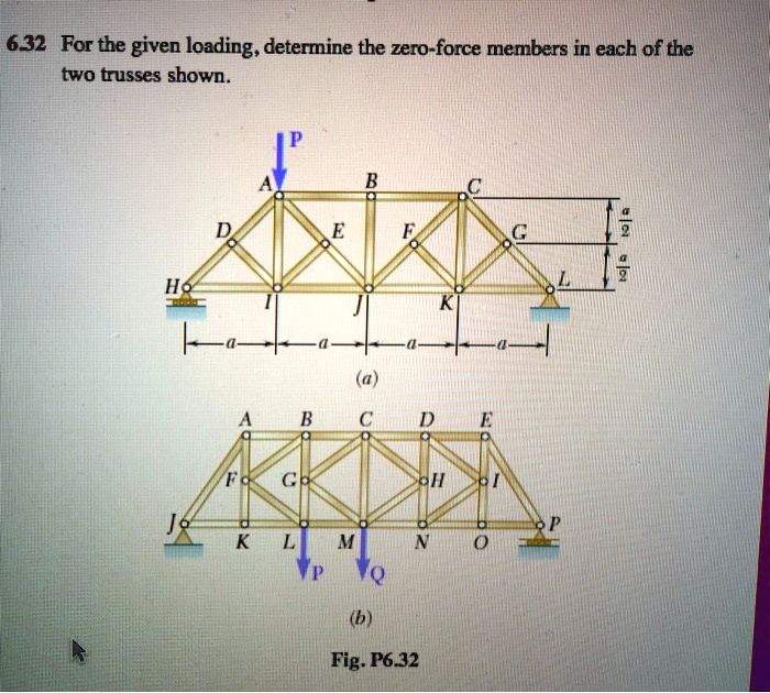
For the given loading, determine the zero-force members in each of the two trusses shown.
The Correct Answer and Explanation is:
Zero-Force Members:
Truss (a): The zero-force members are AD, DG, FG, and GL.
Truss (b): The zero-force members are FG, GH, HI, and IJ.
Explanation:
To determine zero-force members in a truss, we use rules from structural analysis based on the method of joints. These rules are applied at joints where either no external load or support reaction is present.
Rule 1: If two non-collinear members meet at an unloaded joint, both are zero-force members. Rule 2: If three members form a joint and two are collinear, the third member is a zero-force member if there is no external force or support at that joint.
Let us apply these systematically:
For truss (a):
- At joint A, only members AB and AD are connected, and there is no external load. By rule 1, AD is a zero-force member.
- At joint D, with members DE and DG and no applied load, DG is a zero-force member.
- At joint F, members FE and FG meet with no load present, so FG is also zero-force.
- At joint G, with members GK and GL but no load, GL is zero-force.
For truss (b):
- Joint F connects members FA and FG and has no load. Rule 1 implies FG is zero-force.
- At joint G, members GB and GH meet at an unloaded joint. Hence, GH is zero-force.
- Joint H connects HC and HI without external loading, so HI is zero-force.
- Similarly, joint I connects ID and IJ and is unloaded, making IJ a zero-force member.
By identifying these members early, the complexity of force calculations in the rest of the truss can be significantly reduced, making analysis faster and more efficient. This is especially helpful when working manually or simplifying a model for computational methods. Let me know if you’d like a step-by-step breakdown of the internal forces for the remaining members.