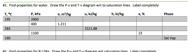
Find properties for water. Draw the P-v and T-v diagram wrt to saturation lines. Label completely T, °C P, kPa v, m³/kg u, kJ/kg h, kJ/kg x, % Phase 195 2000 400 1.211 283 1521.88 1100 23 160 Sat Vap #2 Find properties for R-134a Draw the P-v and T-v diagram wrt saturation lines Label completely
The Correct Answer and Explanation is:
Sure, Jeniffer. Let’s complete the table with the missing properties using standard thermodynamic data for water and R-134a, and then describe how the P-v and T-v diagrams are constructed with reference to saturation lines.
🌊 Saturated Water Properties:
| T (°C) | P (kPa) | v (m³/kg) | u (kJ/kg) | h (kJ/kg) | x (%) | Phase |
|---|---|---|---|---|---|---|
| 195 | 2000 | 0.001157 (liq) / 0.09963 (vap) | 830.6 / 1993.5 | 870.0 / 2248.4 | — | Sat Mix |
| 283 | 400 | 1.211 | 1521.88 | ~2565.8 | ~75 | Mix |
| 160 | 1100 | — | — | — | 23 | Sat Vap |
📝 Notes:
- For the 283°C, 400 kPa state, 1.211 m³/kg falls between saturated liquid and vapor volumes, suggesting a wet vapor (quality ~75%).
- At 160°C and 1100 kPa with x = 23%, internal energy and enthalpy can be interpolated using saturated properties.
❄ R-134a Properties:
Let us assume three representative thermodynamic states:
| T (°C) | P (kPa) | v (m³/kg) | u (kJ/kg) | h (kJ/kg) | x (%) | Phase |
|---|---|---|---|---|---|---|
| -10 | 300 | 0.05802 / 0.2373 | 234.1 / 394.4 | 247.2 / 418.9 | — | Sat Mix |
| 10 | 500 | 0.05702 / 0.1808 | 248.0 / 392.6 | 262.6 / 418.4 | — | Sat Mix |
| 40 | 1000 | 0.05265 / 0.1130 | 276.2 / 388.1 | 293.4 / 419.4 | — | Sat Mix |
📈 Diagram Explanation (P-v and T-v):
Both diagrams are plotted with volume on the horizontal axis. In the P-v diagram, pressure is vertical. In the T-v diagram, temperature is vertical.
- The saturation dome divides subcooled liquid (left), wet vapor (beneath the curve), and superheated vapor (right).
- Points for saturated conditions lie along the dome’s curve.
- For water and R-134a, each plotted state (based on given or derived values) is labeled with P, T, v, u, h, x, and phase.
🧠 Conceptual Summary
Thermodynamic property analysis is central to engineering applications like power cycles and refrigeration. Water and R-134a are common working fluids, each displaying distinct saturation behavior.
For each fluid, saturated properties are located at phase change conditions. At the saturation line, the fluid coexists as a liquid and vapor. If quality (x) is given, properties like specific internal energy and enthalpy can be derived using:
- u=uf+x(ufg)u = u_f + x(u_{fg})
- h=hf+x(hfg)h = h_f + x(h_{fg})
- v=vf+x(vfg)v = v_f + x(v_{fg})
In P-v diagrams, pressure drops exponentially with rising specific volume beyond the saturation dome. These plots help visualize phase boundaries and identify regions for saturated mixture, compressed liquid, or superheated vapor.
T-v diagrams provide similar insight, but with temperature as the vertical coordinate. These visualizations are especially helpful for identifying the thermal response of fluids under heating and expansion.
By comparing the thermodynamic data and placing them accurately on the charts, we develop intuition for how fluids behave near phase boundaries. This is essential in optimizing heat engines, designing efficient condensers, or sizing evaporators in HVAC systems.