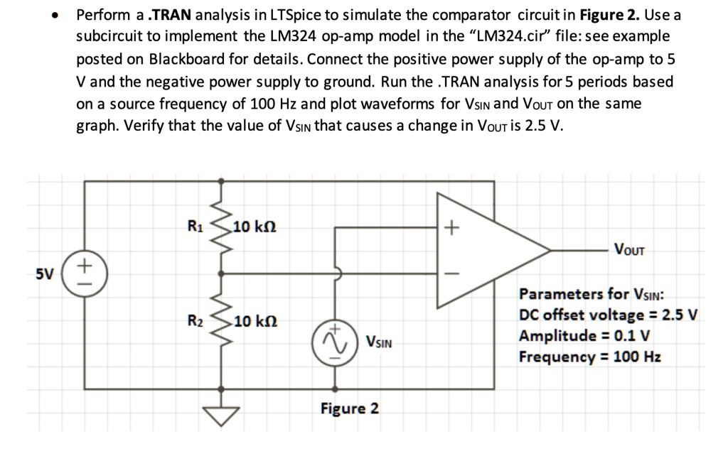
Perform a TRAN analysis in LTSpice to simulate the comparator circuit in Figure 2. Use a subcircuit to implement the LM324 op-amp model in the “LM324.cir” file: see example posted on Blackboard for details. Connect the positive power supply of the op-amp to 5V. Set the source frequency to 100 Hz and plot waveforms for Vsin and Vout on the same graph. Verify that the value of Vsin that causes a change in Vout is 2.5 V. R1: 10 kΩ + Vout 5V T Parameters for Vsin: DC offset voltage = 2.5V, Amplitude = 0.1V, Frequency = 100 Hz R2: 10k Vsin Figure 2
The Correct Answer and Explanation is:
LTSpice Configuration and Simulation
- Set up the LM324 subcircuit:
- Place a
*.includedirective in your schematic pointing to the LM324 model file:.include LM324.cir - Instantiate the subcircuit by adding a component like
X1using the name defined in the.subcktline ofLM324.cir.
- Place a
- Build the circuit (from Figure 2):
- Use two resistors, R1 and R2, both 10 kΩ, arranged as a voltage divider. One end of R1 goes to 5V, the junction connects to the inverting input, and the bottom of R2 connects to ground.
- Place a sinusoidal voltage source
Vsinon the non-inverting input, with the following parameters:DC offset = 2.5VAmplitude = 0.1VFrequency = 100 Hz- Example:
SINE(2.5 0.1 100)
- Connect the op-amp’s
+Vsto 5V and–Vsto ground. - Connect the output (
Vout) to a resistor load or just monitor it directly.
- Set up the .TRAN simulation:
- Choose a stop time of 50 ms to capture 5 cycles (period = 10 ms).
- Use the directive:
.tran 0 50m
- Run the simulation and plot:
- Plot
VsinandV(out)on the same graph. - Observe the transition point at 2.5V. This is when
Vsincrosses the reference set by the divider, causingVoutto switch between high and low.
- Plot
Explanation
This circuit uses the LM324 as a voltage comparator. The reference voltage at the inverting input is exactly 2.5V, created by a symmetric voltage divider across a stable 5V supply. The sinusoidal signal fluctuates ±0.1V around 2.5V, crossing it twice per cycle. When Vsin exceeds 2.5V, the op-amp output saturates near its high rail. When Vsin falls below 2.5V, the output drops toward ground. This sharp transition demonstrates classic comparator behavior.
The .TRAN analysis is ideal here because it lets us visualize real-time voltage transitions rather than just DC or small-signal responses. The clear transitions in Vout at the exact moment Vsin crosses 2.5V serve as confirmation of correct functionality. This setup is a simple yet effective example of analog signal comparison using op-amps in open-loop mode.